
September 12, 2026
the synth didn’t fit on one breadboard
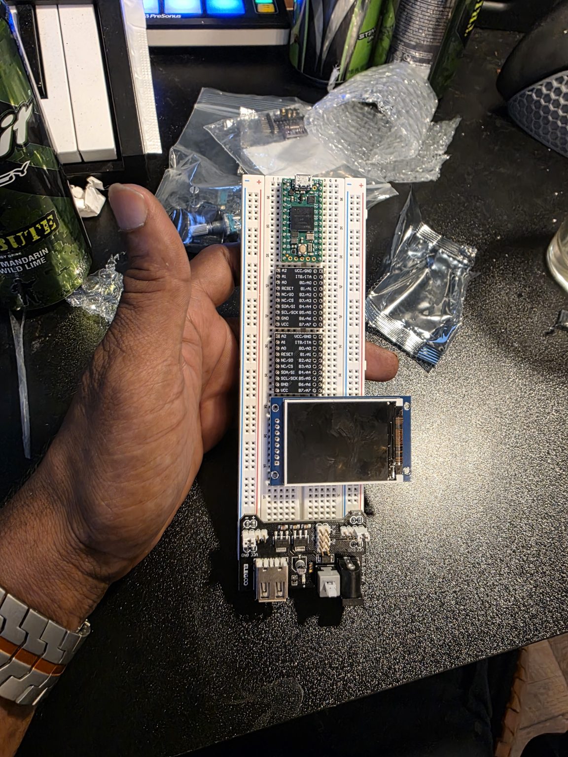
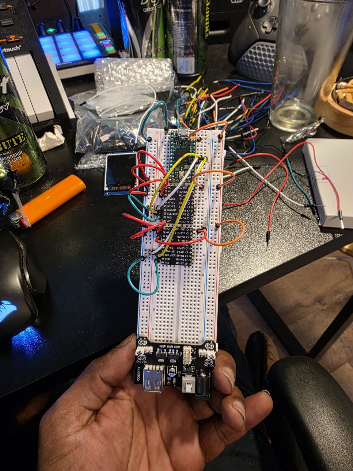
Every component was supposed to fit on a single breadboard. It didn’t take long to find out it wasn’t going to: encoders, a display, buttons, and all the wiring between them were fighting over the same rows, and the board ran out before the parts did. So the display came off and the rest of the wiring went floating, which is plan B — the same plan, with the parts hanging in the air. That’s when the wiring stopped being a chore and became the actual project. Everything after that is wiring with extra steps.
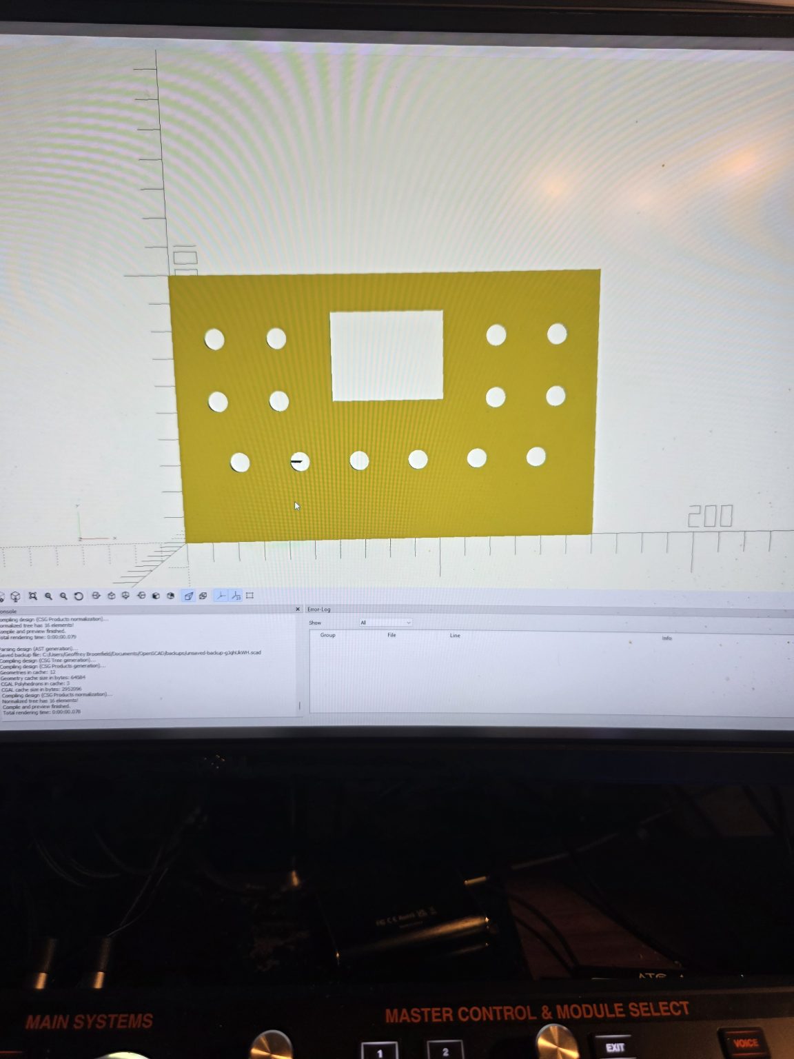
The case came off a printer on my desk. It wasn’t a considered decision. The first faceplate fit the board and not the screen, because I hadn’t printed the standoffs that hold the screen in, so it got electrical tape, and the tape held. I’m not going to pretend that was the plan. rev1 didn’t have enough knobs either. I built a synthesizer and forgot that synthesizers have knobs. That’s why rev2 exists, and rev2 was a SCAD file for a while before it was an object.
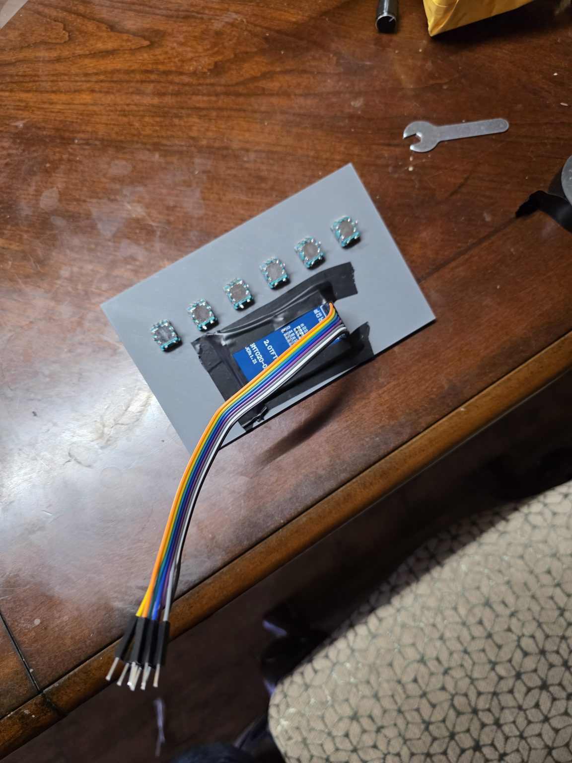
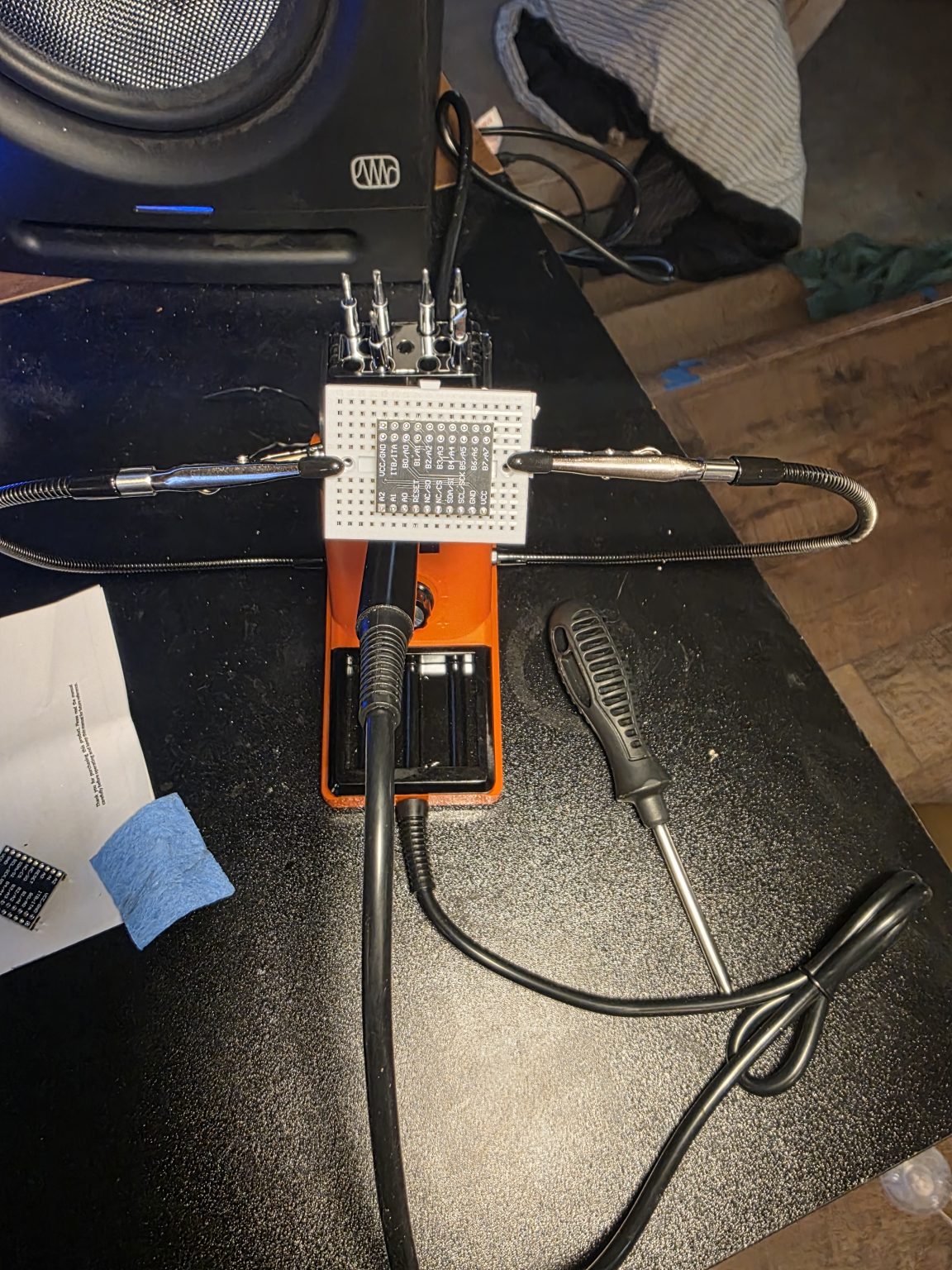
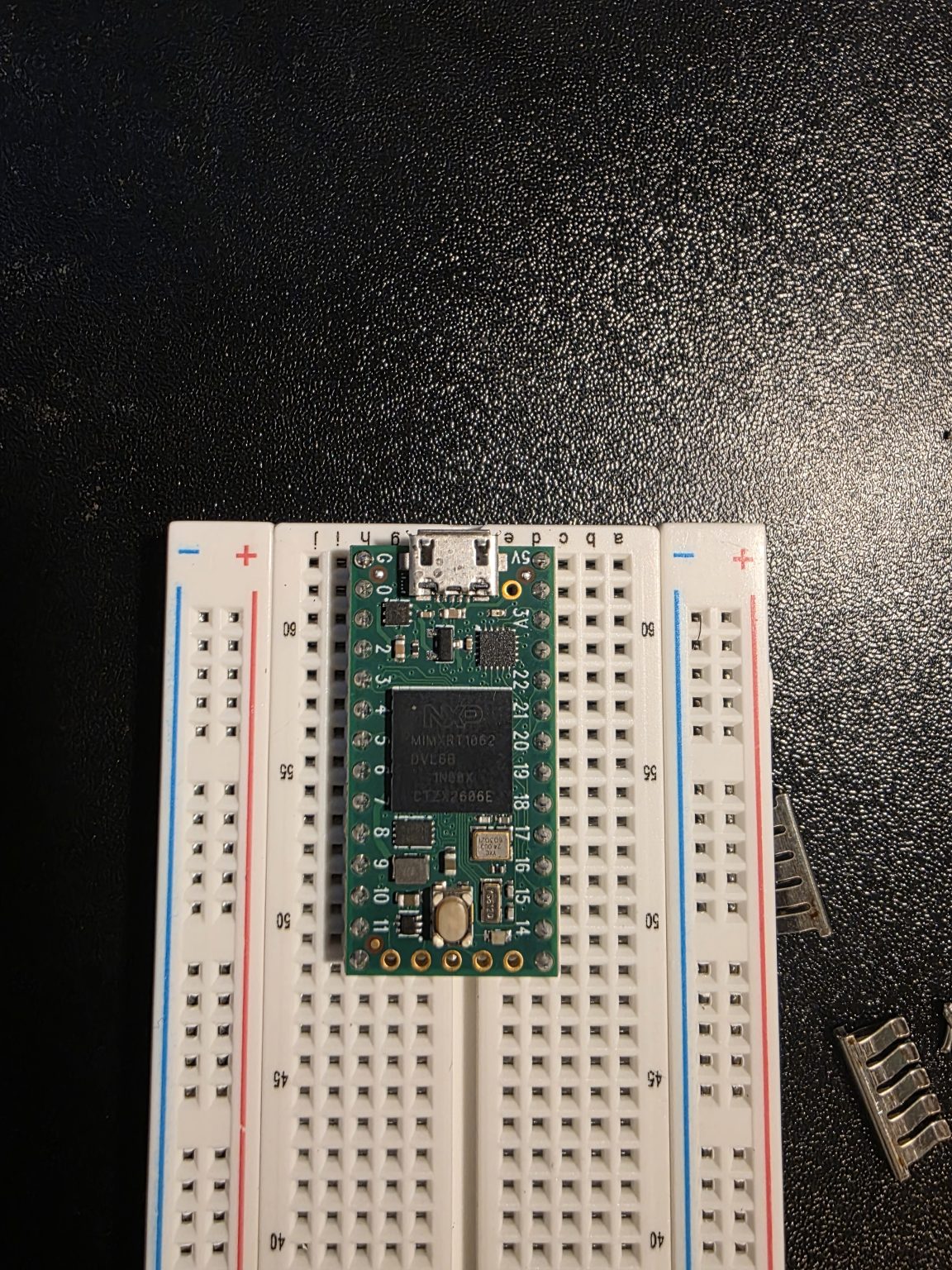
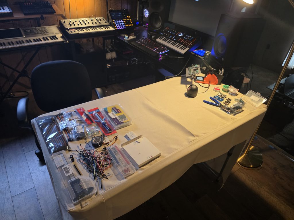
The encoders and buttons run through MCP expanders, so I spent a few nights soldering pins onto those. The board itself spent that time back on the breadboard with everything taken off it, which about sums up how the plan was going. None of this happened in a workshop. The soldering desk is the dining room, because that’s the budget, and I’ve made my peace with it.
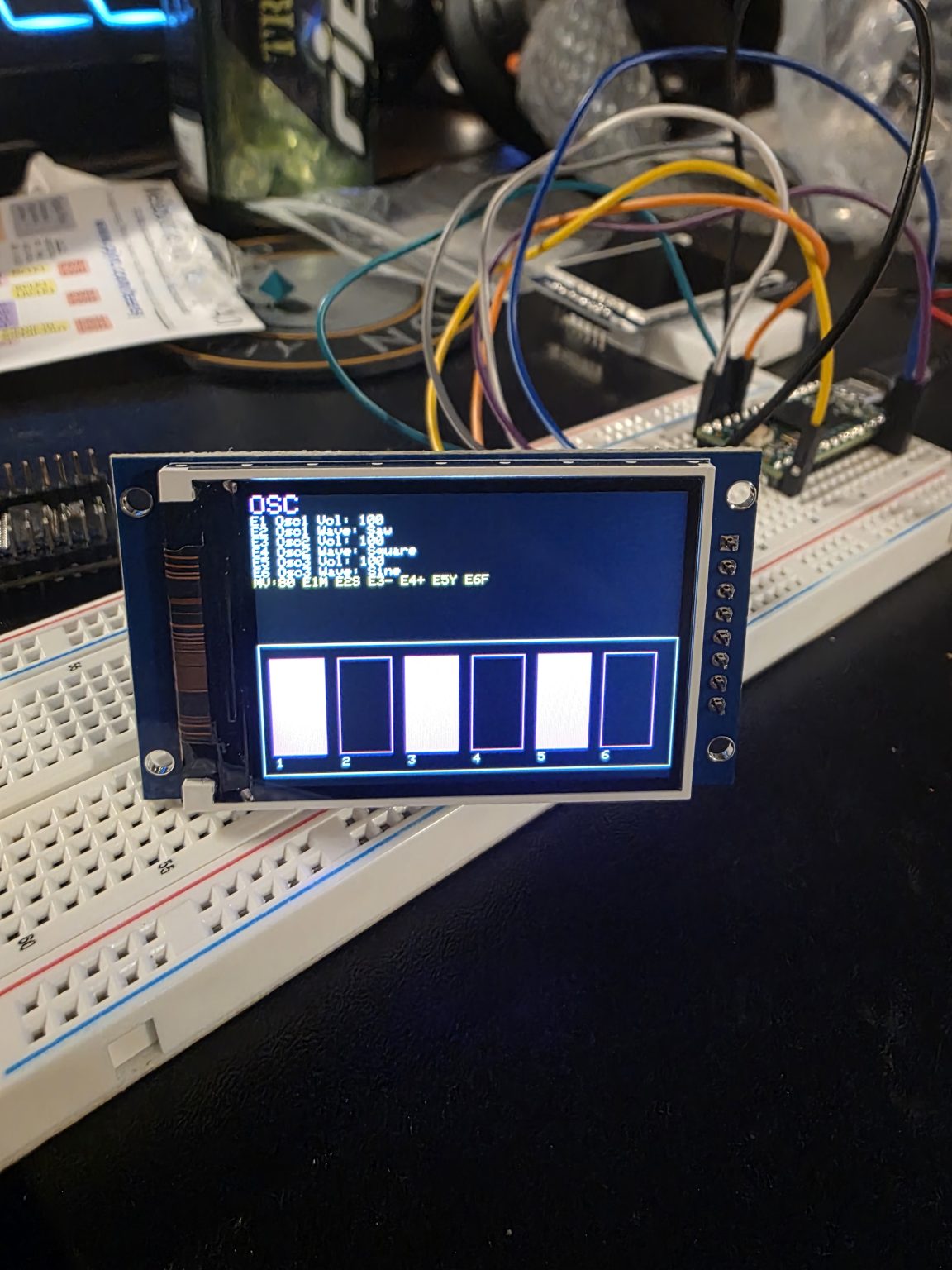
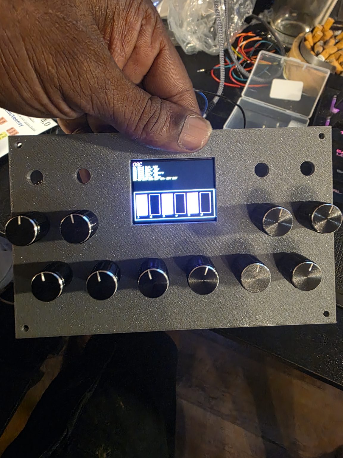
At 2:37 in the morning on August 9, the synth engine ran on hardware for the first time. The interface is rough and the photo is dark, and both are true. The LCD fit the rev2 faceplate with four knobs still missing. I colored the sliders in and added a pile of features, which is how I figured out that features need menus. Nobody warns you that features need somewhere to live.
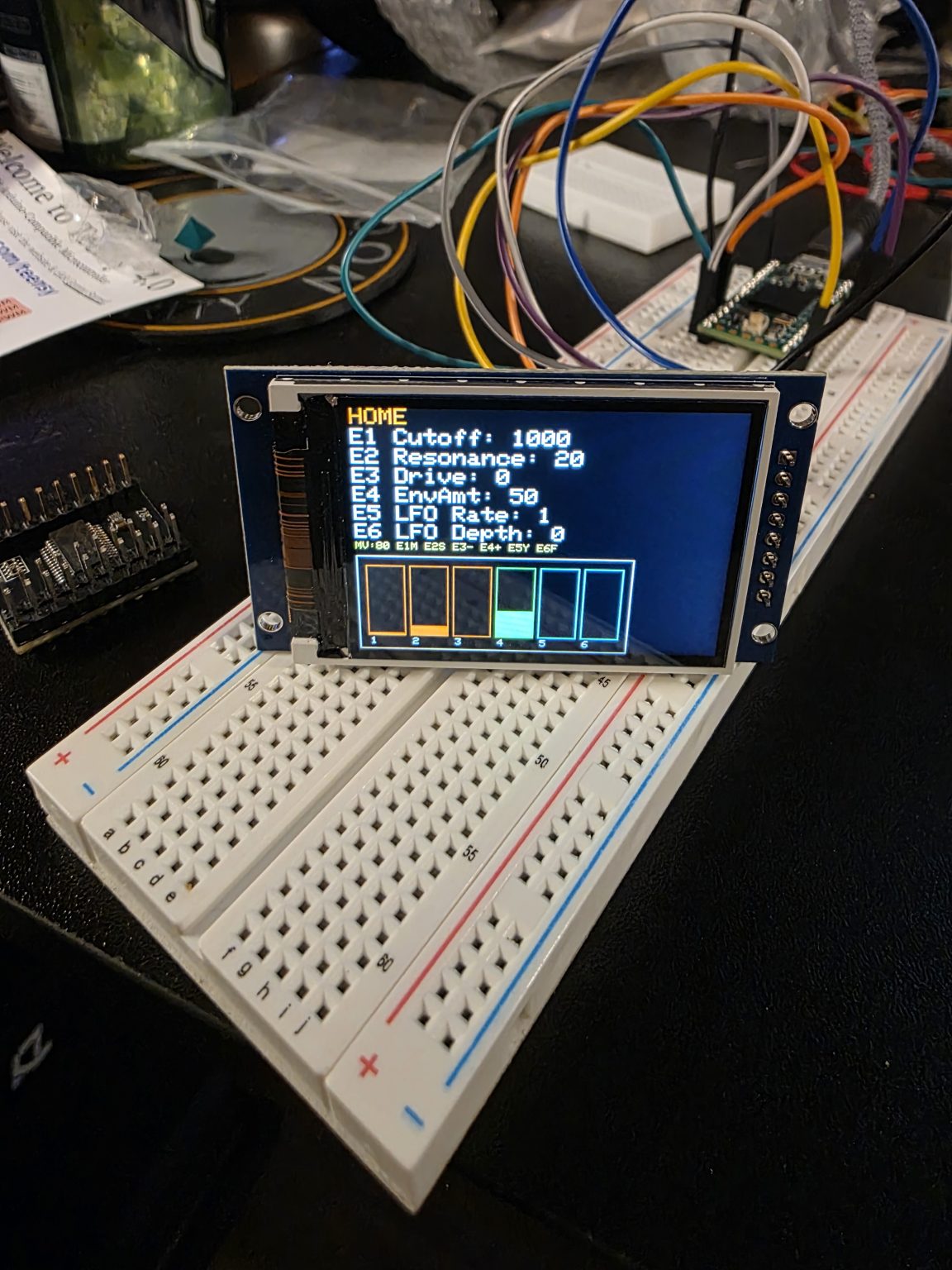
Menus don’t cooperate. I found that out over several days, having already built the features that needed them. What follows is the rest of that night and most of the week after: rev2 of the interface, then rev2.5 with context labels along the bottom, then more of the same that afternoon with the menus still not cooperating. They’re all shot against the grey faceplate, because that was the only way to see how the interface would look.
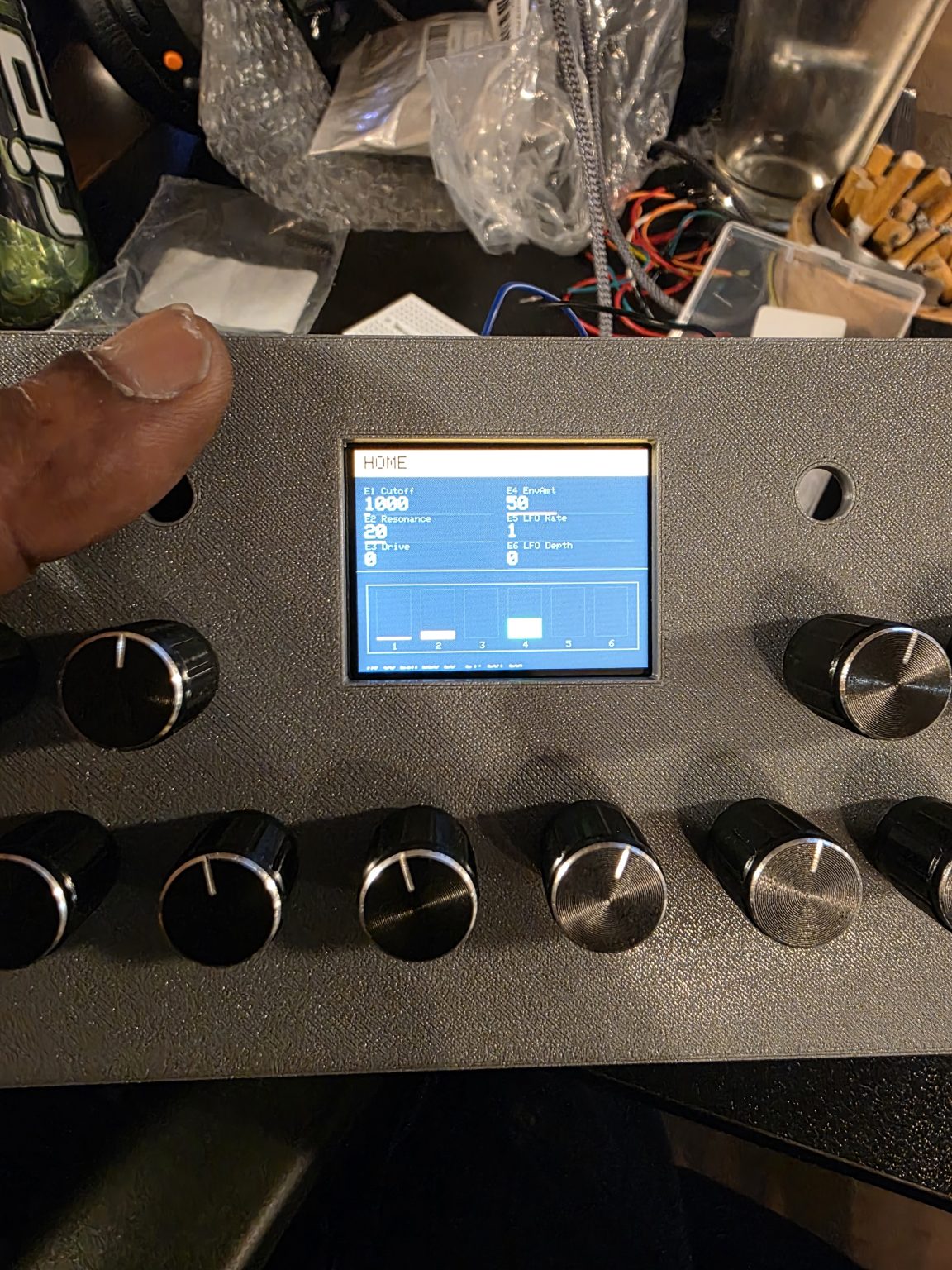
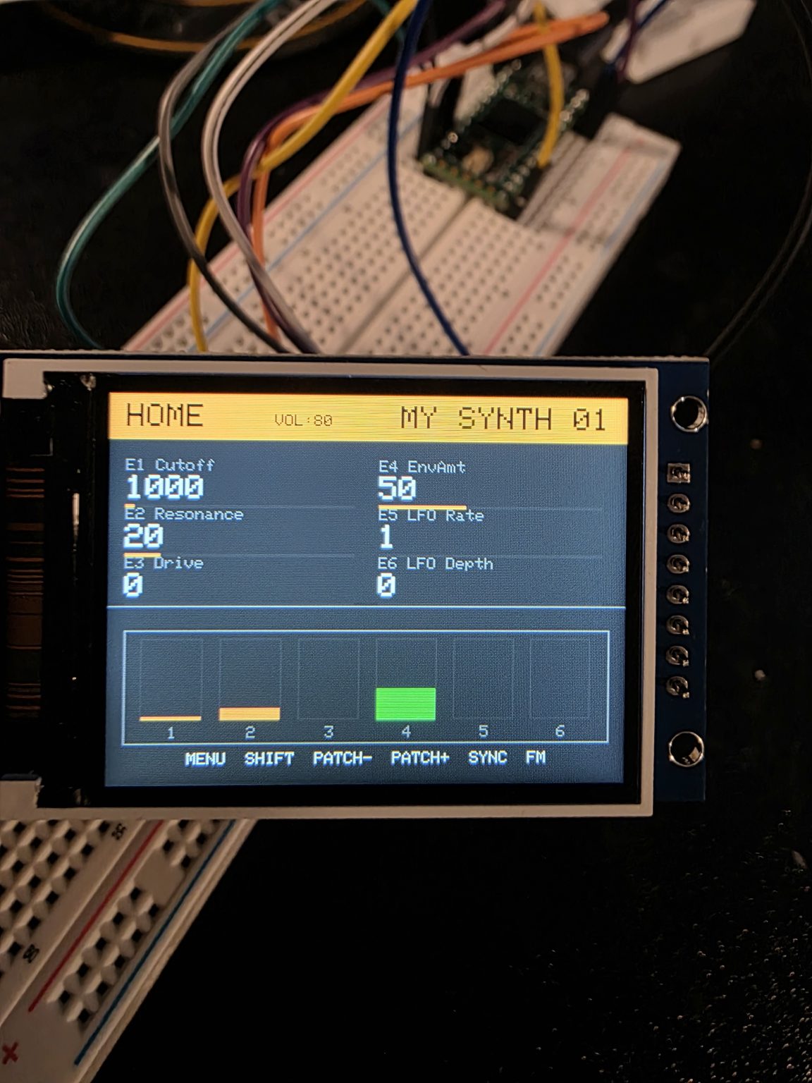
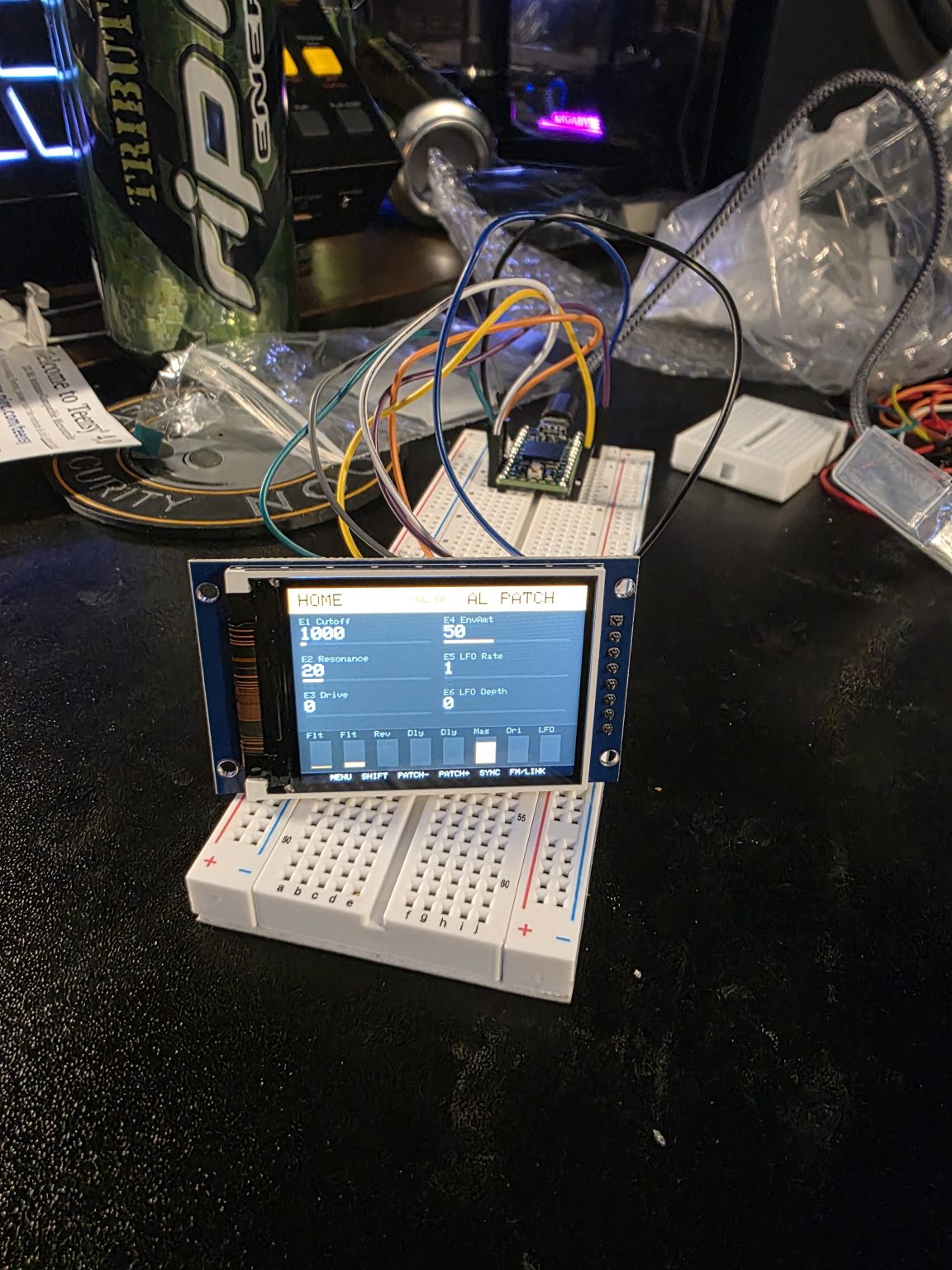
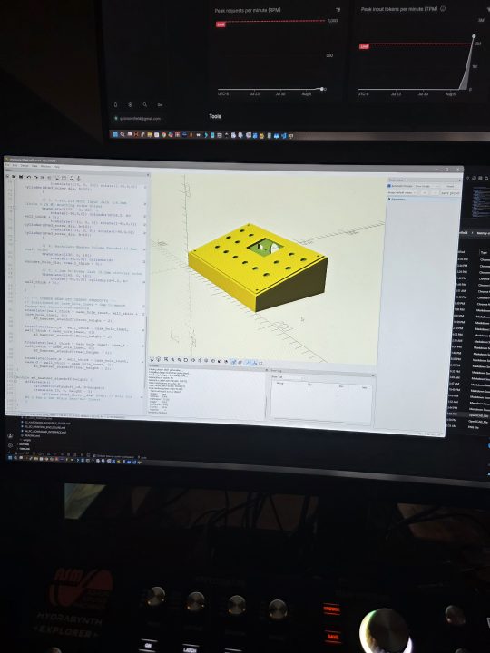
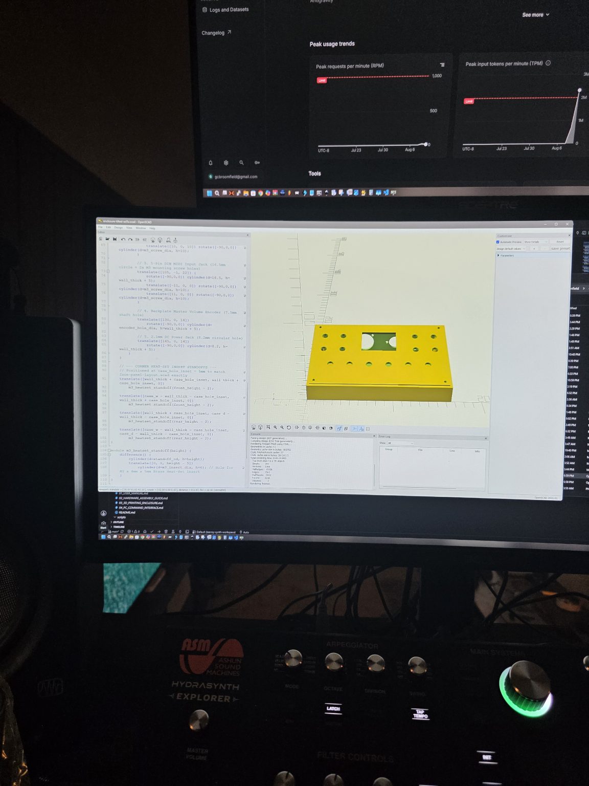
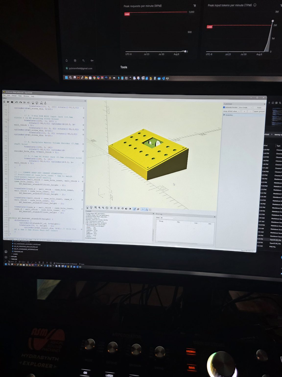
While I was fighting the menus, the case got drawn: a front view and a three-quarter view, both still in SCAD, both still way cheaper to change than a printed part. Drawing it is the part of this I’m actually good at.
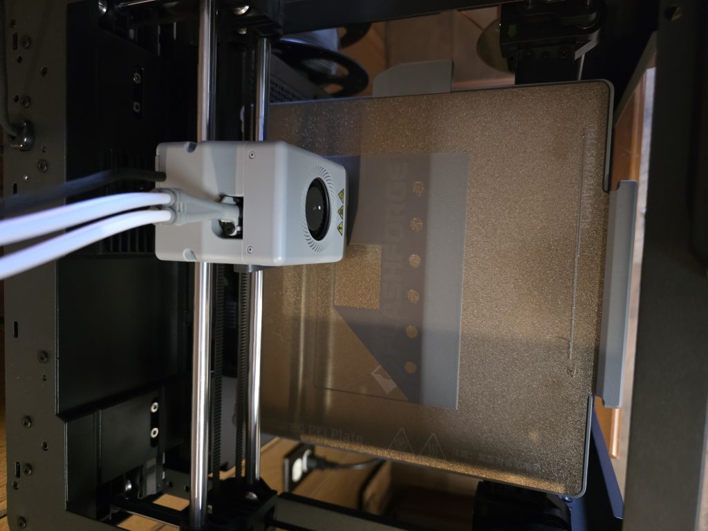
Three clips survived. Between them they cover what a photo can’t. One is the printer running, making a replacement for a faceplate I broke, which is entirely on me. Another is a power-on test, mostly about the wake-up screen, which was crashing the UI. The last is fifty-two seconds of the menus finally responding to knobs and presses, after hours of fighting them. That’s the one I’d show somebody.
So: the components never fit on one breadboard, the faceplate was wrong twice, and the menus took almost a week. It works now. I’m aware all three of those were my fault.